Part II: Removing the top cover
With the keyboard removed, the state of the computer is shown in Fig. 8a. Remove the six short screws indicated at the 'A's in Fig. 8, the five medium-length screws indicated at the 'B's, and finally the single long screw indicated at the 'C'. The relative lengths of these screws are shown in detail in Fig. 8b.
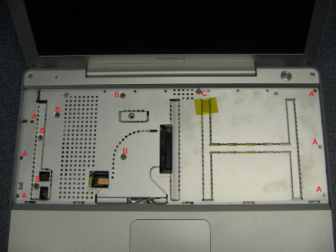
Figure 8a. The PowerBook G4 12" with its keyboard removed. Remove the six short screws indicated at the 'A's, the five medium-length screws indicated at the 'B's, and finally the single long screw indicated at the 'C'.
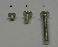
Figure 8b. The relative lengths of the screws indicated in Fig. 8a.
In the lower left corner of the exposed keyboard area, as shown in Fig. 9a, there are three connectors that need to be disconnected in order to proceed. Lift up and disconnect the two smaller-type connectors, as shown in Fig. 9b. One is for the power button (red/black wires) and the other one is the connector for the microphone (black/grey wires). Also lift the bigger connector with the loop of yellowish plastic foil, as shown in Fig. 9c. This is the connector to the touch-pad pointing device.
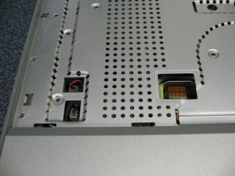
Figure 9a. In the lower left corner there are three connectors that need to be disconnected.
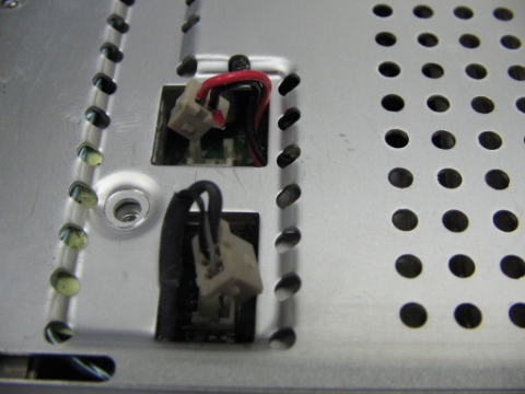
Figure 9b. Remove the connector for the power button (red/black wires) and the connector for the microphone (black/grey wires).
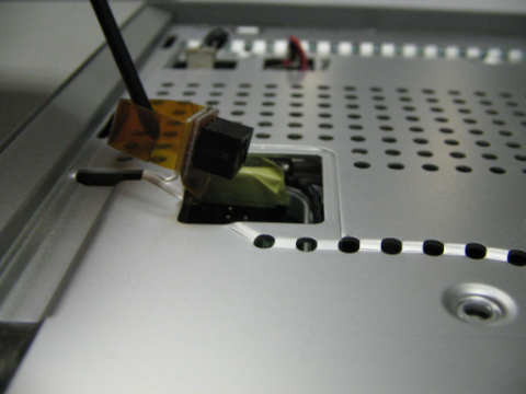
Figure 9c. Lift out the yellowish plastic loop of the touch pad connector and pull it straight up to disconnect.
The top cover is still fixed to the chassi of the computer. In order to remove the cover, remove the two Phillips screws located at the right-hand side just above the battery compartment, as shown in Fig. 10a. Remove the two Phillips screws located at the left-hand side close to the slot for the Kensington lock, as shown in Fig. 10b. For the future re-assembly of the computer, it might be an idea to note that the right-hand side screws are slightly shorter than those at the left-hand side, as shown in Fig. 10c. Finally also remove the four screws at the rear side of the computer.
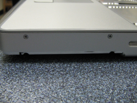
Figure 10a. Remove the two screws located on the right side just above the battery compartment.
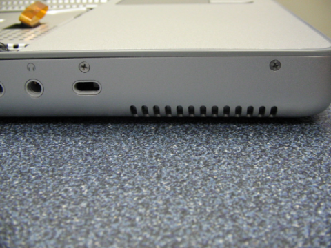
Figure 10b. Remove the two screws located on the left side close to the slot for the Kensington lock.
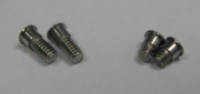
Figure 10c. The two screws removed from the right (battery-compartment) side are slightly shorter than the ones removed from the left side.
Now remove the two hex screws visible at the top cover close to the top edge corners. Again, the right corner screw is longer than the left corner one. It should now be possible to separate the top cover slightly from the chassi, as shown in Fig. 11a. Grab the top cover by the top edge and gently lift out the cover as shown in Fig. 11b. You will as in the case with the keyboard feel a slight resistance, as the cover also is additionally fixed from the inside with doubly adhesive tape. However, in this case you must pay extra attention to the bottom edge, as this is fixed to the chassi by plastic snap locks which very easily breaks. At the bottom edge, slide your nail or a soft plastic tweezer between the top cover and the chassi to separate them. By no means try to remove the cover by tilting it by force. The snap locks at the bottom edge of the chassi are shown in Fig. 11c, pictured after the cover was removed.
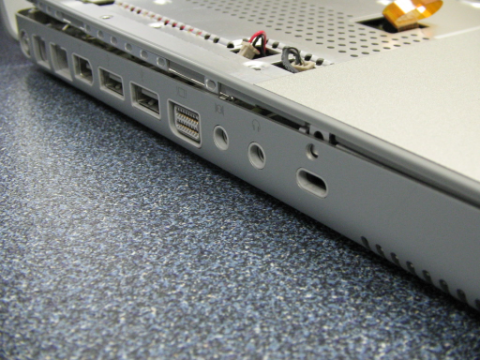
Figure 11a. The top cover should now be possible to separate slightly from the chassi.
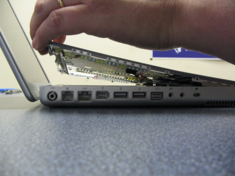
Figure 11b. Grab the top cover by the top edge and gently lift out the cover. However, make sure that the plastic snap locks at the bottom edge of the cover are properly released, as they otherwise easily may break.
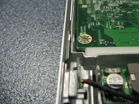
Figure 11c. One of the plastic snap locks at the bottom edge of the chassi, holding the bottom edge of the top cover in place.
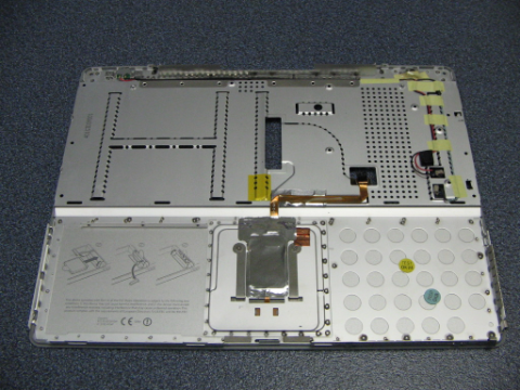
Figure 11d. The top cover seen from the bottom side.